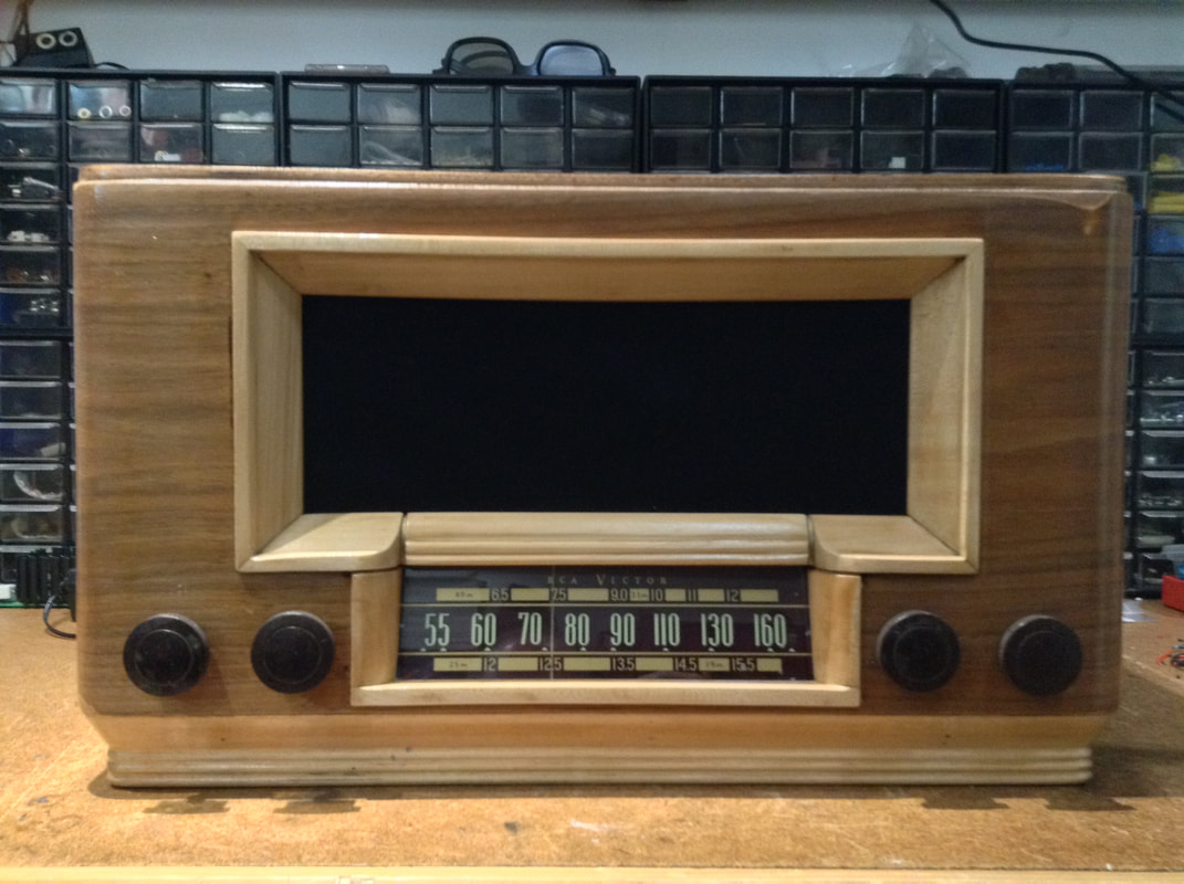
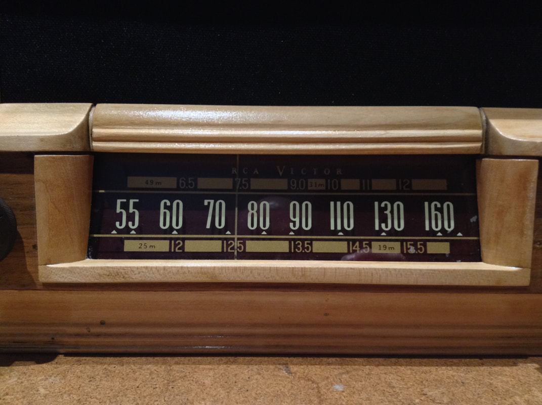
RCA Model 50
This is an old 3-band tube radio, from the early 1940s. Made by RCA Victor in Montreal, Canada. It arrived in my garage from my father-in-law's grandmother's cousin (I think). It was in rough shape - water damage, broken wires, lots of dust, old capacitors, and no schematic. It sat in my warehouse for at least 5 years, but then I finally got the bug to rebuild it.
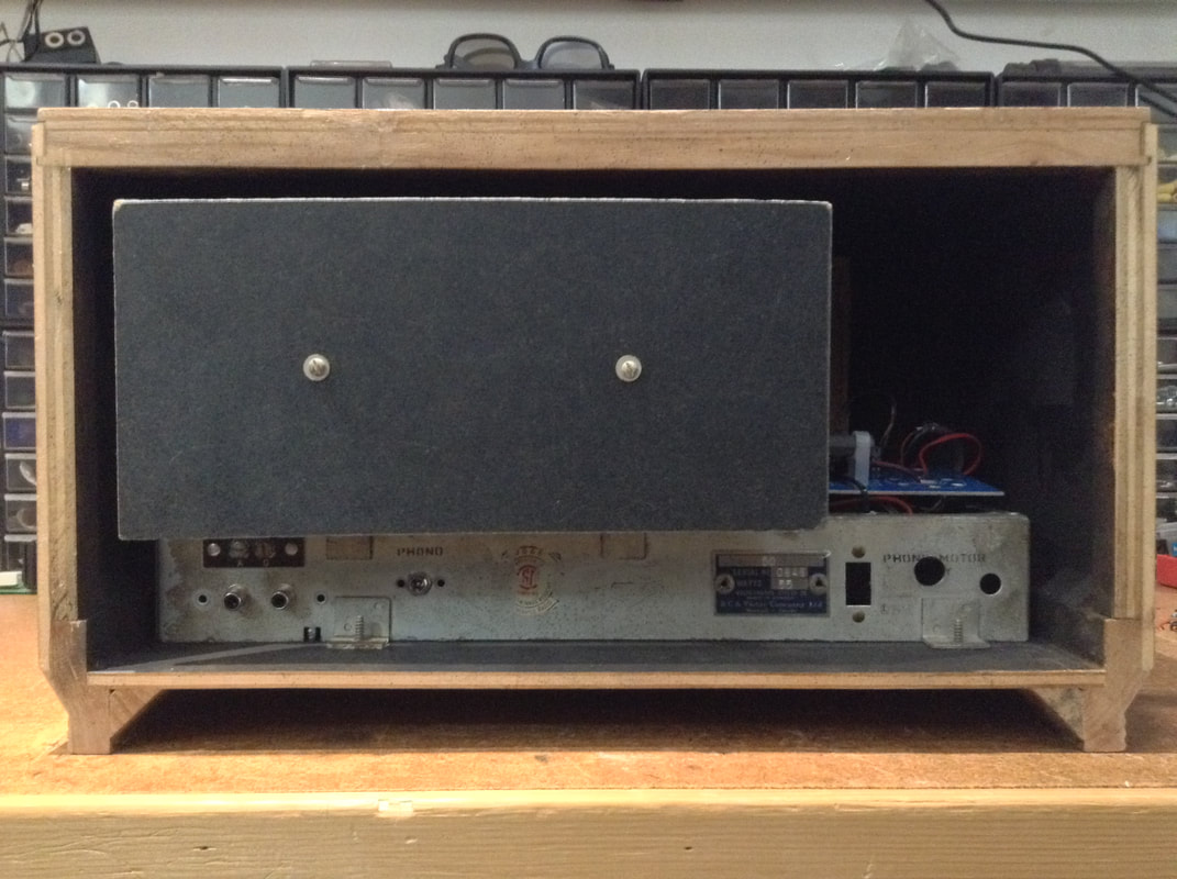
My son and I took it all apart. We sanded the damaged finish off the wood, and maybe went a little too far in a couple of places. The original trim around the speaker and the base were black, and the cloth in the middle was a light tweed. The paint came off quite easily and we liked the colour so we left it. The black cloth gives a nice contrast. The knobs are a bit scratched up and I didn't want to replace them, so we cleaned them up and re-used them.
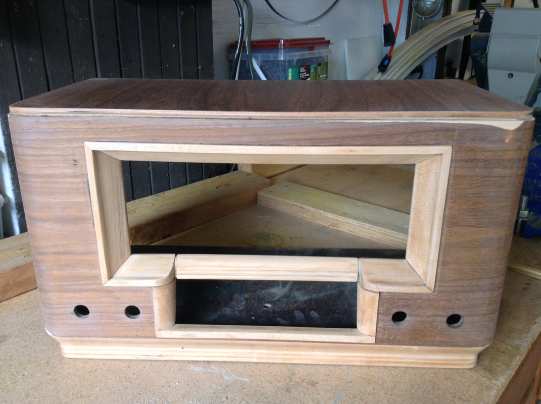
There's no pictures of the chassis here, or anything before we started fixing it up. I hadn't really thought about taking pictures at that time. It's just as well - some of the radio junkies out there will be offended at what happens next. This picture is after sanding, before 3 coats of varathane.
There's no pictures of the chassis here, or anything before we started fixing it up. I hadn't really thought about taking pictures at that time. It's just as well - some of the radio junkies out there will be offended at what happens next. This picture is after sanding, before 3 coats of varathane.
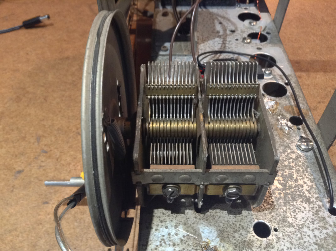
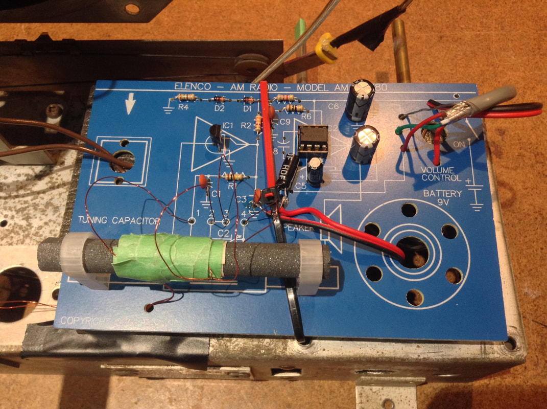
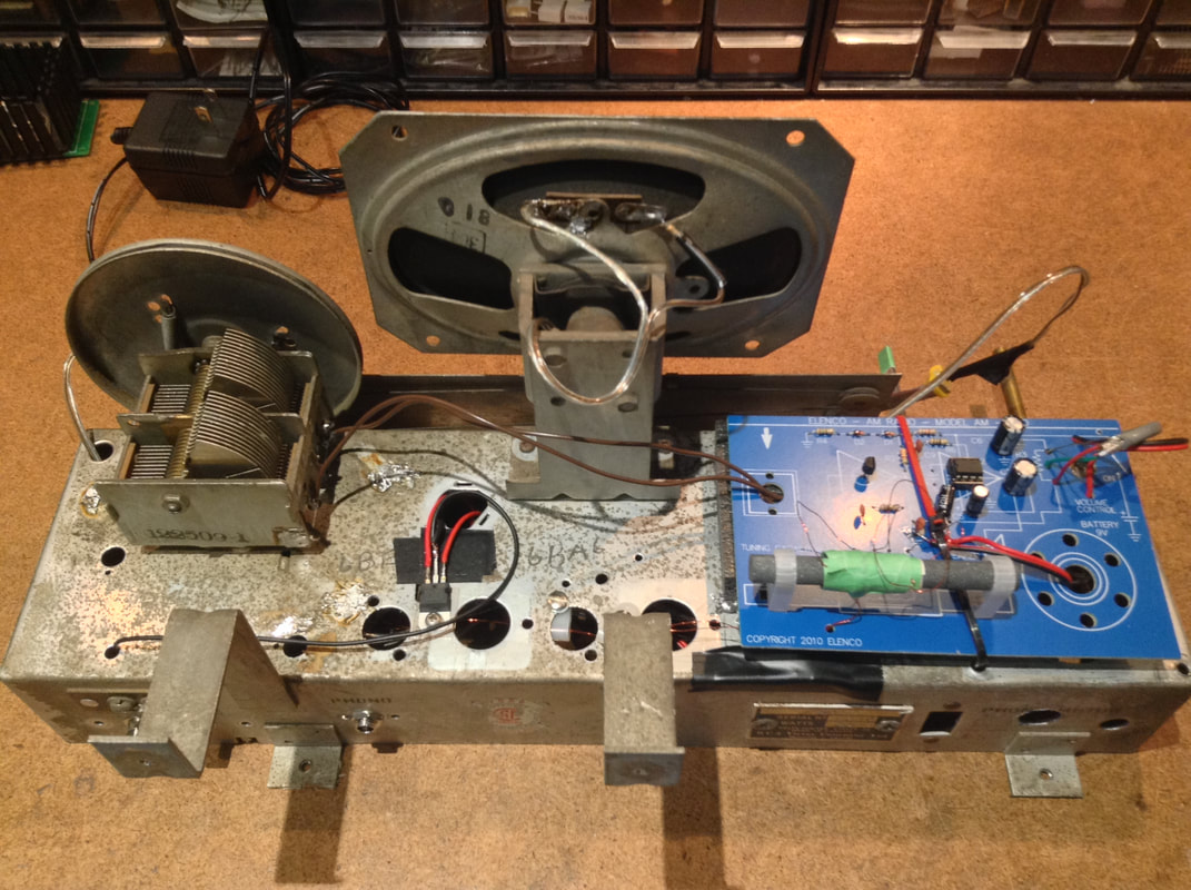
I bought an AM-780 radio kit from Elenco (the new Radio Shack). Nice and simple. I wanted to use the original tuning mechanism (and tuning capacitor) and I wasn't sure I would be able to get the super-het kit (AM-550) to work with the capacitor from this radio. In the end, I used the tuning capacitor from this radio, but I had to wind a new coil on the ferrite bar from the kit. First try came close - wind a few less turns than you think you need and tape it in place. Then you can wind a shorter second coil to get the tuning range correct.
|
|
|
If you look carefully, I was able to use the existing coil connections for my home-made coil. The gain capacitor on the audio circuit has not been used, and there's some extra wires coming through the board where the speaker is supposed to be - I'll get to that later.
The radio kit covers the main band of the RCA radio, 550 to 1600 kHz. The other two bands of the RCA radio are 6.5 Mhz to 12 Mhz and 12 MHz to 15.5 MHz which are well beyond the range of the the kit. The kit uses a TA7642 (ZN414, MK484) which is a little AM radio receiver chip - you just provide the tuning. It's good up too about 3 Mhz by itself, but I have read of people using it as the final stage of a short-wave super-het receiver.
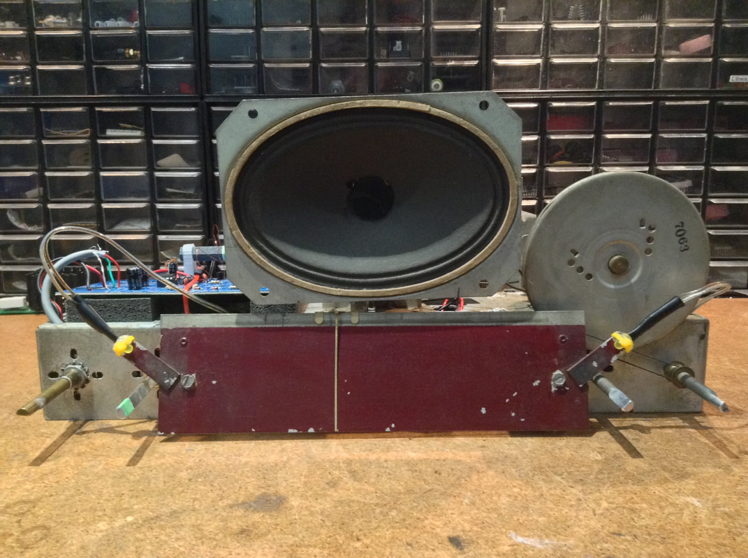
I was able to use the original speaker, but I had to add a resistor in series with it. The original speaker is about 3 Ohms and the LM386 audio amplifier in the kit is not stable with a load that small.
The radio kit covers the main band of the RCA radio, 550 to 1600 kHz. The other two bands of the RCA radio are 6.5 Mhz to 12 Mhz and 12 MHz to 15.5 MHz which are well beyond the range of the the kit. The kit uses a TA7642 (ZN414, MK484) which is a little AM radio receiver chip - you just provide the tuning. It's good up too about 3 Mhz by itself, but I have read of people using it as the final stage of a short-wave super-het receiver.
I was able to use the original speaker, but I had to add a resistor in series with it. The original speaker is about 3 Ohms and the LM386 audio amplifier in the kit is not stable with a load that small.
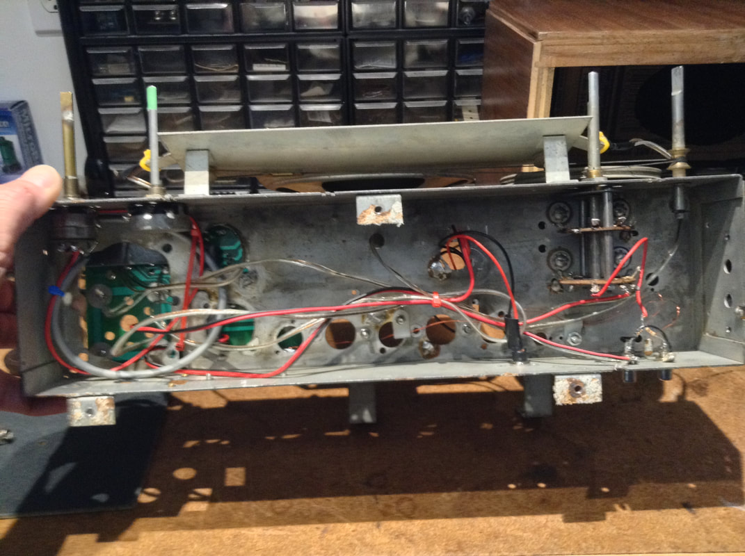
There's only wires under the metal frame - all the tubes, transformers, etc were removed - not very gracefully. The tube sockets and some of the RF coils were riveted to the chassis, so I had to drill them out and use vice grips. Just so no-one feels too bad, the RF coils and much of the wiring was crumbling, just from looking at it. I don't know where this was stored, but probably on the floor of a garage or shed for 50 years. Nothing came out in one piece. This is the first radio I have disassembled where the tuning mechanism is intact, so I touched nothing there.
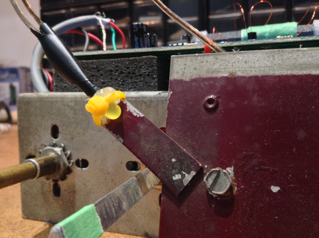
I used yellow LEDs instead of light bulbs. The original radio was rated at 55W on the CSA plate. I think this will come in around 100mW when it's finished. This radio will run for months on a 9V battery.
I used yellow LEDs instead of light bulbs. The original radio was rated at 55W on the CSA plate. I think this will come in around 100mW when it's finished. This radio will run for months on a 9V battery.
|
|
|
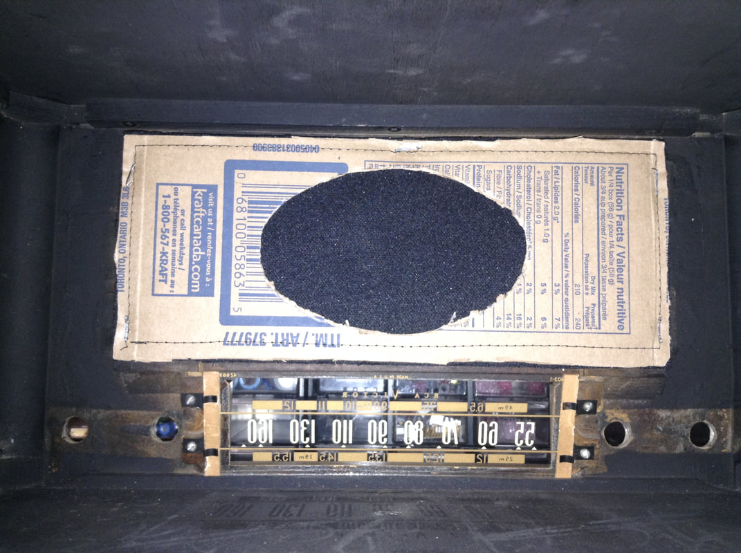
My daughter sewed a piece of grill cloth to some cardboard. The cardboard was cut using the original as a template. Then I stapled it to the inside of the cabinet. I replaced the antenna board with a piece of masonite - mostly to keep fingers out.
|
|
|
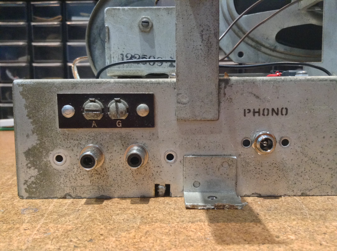
You may notice a couple of RCA jacks under the antenna terminals. I've used all the original controls in this build. The volume control is the original 1 MOhm variable resistor. There is a 4 position switch that was used to select among the 3 different radio bands and a Phono input, so I have used it to switch between the radio and the RCA input. It works well for an iPod or bluetooth receiver.
The gain capacitor I mentioned earlier is only needed if the kit circuit board is used by itself with a small speaker. In a box, with a larger speaker, it is plenty loud. The remaining knob on the front is for a tone control, which I have not used here, but it is in place to finish the radio.
There's a 2.5mm barrel connector for a power supply. I had a 9V, 300mA suppy, but at low current it runs around 15V, so I put a 7809 regulator in there as well.
The antenna connector is also used - 3 turns of wire around the ferrite, one end tied to the negative supply and the G terminal, the other end tied to the A terminal.